Intel 8086 : 8086 Instruction Set , Data Transfer Instructions , Arithmetic Instructions , Bit Manipulation Instructions and String Instructions
9.5 8086 Instruction Set
The 8086 has approximately 117 different instructions with about 300 op-codes. The 8086 instruction set contains no-operand, single-operand, and two-operand instructions. Except for string instructions that involve array operations, 8086 instructions do not permit memory-to-memory operations. Appendices F and H provide 8086 instruction reference data and the instruction set (alphabetical order), respectively. The 8086 instructions can be classified into eight groups:
1. Data Transfer Instructions
2. Arithmetic Instructions
3. Bit Manipulation Instructions
4. String Instructions
5. Unconditional Transfer Instructions
6. Conditional Branch Instructions
7. Interrupt Instructions
8. Processor Control Instructions
Let us now explain some of the 8086 instructions with numerical examples. Note that

in the following examples , symbol ( ) is used to indicate the contents of a register or a memory location.
9.5.1 Data Transfer Instructions
Table 9.1 lists the data transfer instructions. Note that LEA is used to load 16-bit offset to a specified register; LDS and LES are similar to LEA except that they load specified register as well as DS or ES. As an example, LEA BX, 3000H has the same meaning as MOV BX,3000H. On the other hand, if (SI)=2000H, then LEA BX,4[Sl] will load 2004H into BX while MOV BX,4[SI] will initialize BX with the contents of memory locations computed from 2004H and DS. The LEA instruction can be useful when memory computation is desirable.
In Table 9.1, there are 14 data transfer instructions. These instructions move single bytes and words between a register, a memory location, or an I/0 port. Let us explain some of the instructions in Table 9.1.
- MOV CX, DX copies the 16-bit contents ofDX into ex. MOV AX, 2025H moves immediate data 2025H into the 16-bit register AX. MOV eH, [ BX] moves the 8-bit contents of a memory location addressed by BX in segment register DS into eH. If (BX) = 0050H, (DS) = 2000H, and (20050H) = 08H, then, after MOV eH, [ BX], the contents ofeH will be 08H. MOV START [BP], ex moves the 16-bit (eL to first location and then eH) contents of ex into two memory locations addressed by the sum of the displacement START and BP in segment register SS. For example, if (eX) = 5009H, (BP)=0030H, (SS) = 3000H, and START= 06H, then, after MOV START [ BP l , ex, (30036H) = 09H and (30037H) =SOH.
LDS s I, [ 0 01OH] loads SI and DS from memory. For example, if (DS) = 2000H, (20010) = 0200H, and (20012) = 0100H, then, after LOS SI, [0010], Sl and DS will contain 0200H and 0100H, respectively.
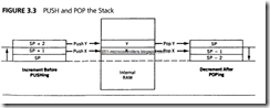
In the 8086, the SP is decremented by 2 for PUSH and incremented by 2 for POP. For example, consider PUSH [BX]. If (DS) = 2000 16, (BX) = 020016, (SP) = 300016, (SS) = 4000 16, and (20200) = 012016, then, after execution of PUSH [BX], memory locations 42FFF and 42FFE will contain 01 16 and 20 16,respectively, and the contents of SP will be 2FFE 16• XCHG has three variations: XCHG reg, reg and XCHG mem, reg or XCHG reg, mem.
For example, XCHG AX, BX exchanges the contents of 16-bit register BX with the contents of AX. XCHG mem, reg exchanges 8- or 16-bit data in mem with 8-or 16-bit reg.
XLAT can be used to employ an index in a table or for code conversion. This instruction utilizes BX to hold the starting address of the table in memory consisting of 8-bit data elements. The index in the table is assumed to be in the AL register. For example, if (BX) = 0200 16, (AL) = 0416, and (DS) = 300016, then, after XLAT, the contents of location 30204 16 will be loaded into AL. Note that the XLAT instruction is the same as MOV AL, [AL] [ BX] . As mentioned before, XLAT instruction can be used to convert from one code to another. For example, consider an 8086-based microcomputer with an ASCII keyboard connected to Port A and an EBCDIC printer connected to Port B. Suppose that it is desired to enter numerical data via the ASCII keyboard, and then print them on the EBCDIC printer. Note that numerical data entered into this computer via the keyboard will be in ASCII code. Since the printer only understands EBCDIC code, an ASCII to EBCDIC code conversion program is required. The ASCII codes for numbers 0 through 9 are 30H through 39H while the EBCDIC codes for numbers 0 to 9 are FOH to F9H (Table 2.6). The EBCDIC codes for the numbers 0 to 9 can be stored in a table starting at an offset 2030H , data can be input from the keyboard using IN AL, PORTA, convert this ASCII data to EBCDIC using XLAT instruction, and then output to Port Busing OUT PORTB, AL. The instruction sequence for the code conversion program is provided below:

For variable port addressing, the port address is 16-bit and is specified in the DX register. Assume (DX) = 312416 in all the following examples.
IN AL, DX inputs 8-bit data from 8-bit port 312416 into AL.
IN AX, DX inputs 16-bit data from ports 312416 and 312516 into AX.
OUT DX, AL outputs 8-bit data from AL into port 312416• OUT DX, AX outputs 16-bit data from AX into ports 312416 and 3125 16• Variable port addressing allows up to 65,536 ports with addresses from 0000H to FFFFH. The port addresses in variable port addressing can be calculated dynamically in a program. For example, assume that an 8086-based microcomputer is connected to three printers via three separate ports. Now, in order to output to each one of the printers, separate programs are required if fixed port addressing is used. However, with variable port addressing, one can write a general subroutine to output to the printers and then supply the address of the port for a particular printer in which data output is desired to register DX in the subroutine.
9.5.2 Arithmetic Instructions
Table 9.2 shows the 8086 arithmetic instructions. These operations can be performed on four types of numbers: unsigned binary, signed binary, unsigned packed decimal, and signed packed decimal numbers. Binary numbers can be 8 or 16 bits wide. Decimal numbers are stored in bytes; two digits per byte for packed decimal and one digit per byte for unpacked decimal with the high 4 bits filled with zeros.
Let us explain some of the instructions in Table 9.2.
- Consider ADC mem/reg , mem/reg. This instruction adds source and destination data along with the carry flag, and stores the result in destination. There is no ADC mem , mem instruction. All flags in the low byte of the Flag register are affected. For example, if (AX) = 0020 16, (BX) = 0300 16> CF = I, (DS) = 2020 16, and (20500) = 0 I 0016, then, after ADC AX, [BX] , the contents of register AX = 0020 + 0 I 00 + I = OI21 16; CF = 0, PF = 0 (Result with odd Parity), AF = 0, ZF = 0 (Nonzero Result), SF = 0 (Most Significant bit of the result is zero), and OF = 0.
- Consider SBB mem/reg , mem/reg. This instruction subtracts source data and the carry flag from destination data, and stores the result in destination. There is no SBB mem, mem instruction. All flags in the low byte of the Flag register are affected. For example, if(CH) = 0316, (DL) = 0216, and CF =I, then, after SBB CH,DL, the contents of register CH = 03- 02- I= 0016•

- The Compare (CMP) instruction subtracts source from destination providing no result of subtraction; all status flags are affected based on the result. Note that the SUBTRACT instruction provides the result and also affects the status flags. Consider CMP DH, BL. If prior to execution of the instruction, (DH) = 40H and (BL) = 30H then after execution of CMP DH, BL, the flags are: CF = 0, PF = 0, AF = 0, ZF = 0, SF = 0, and OF= 0; result 1OH is not provided. Suppose it is desired to find the number of matches for an 8-bit number in an 8086 register such as DL in a data array of 50 bytes in memory pointed to by BX in DS. The following instruction sequence with CMP DL, [ BX] rather than SUB DL, [ BX] can be used :


In the above, ifSUB DL, [BX) wereused instead of CMP DL, [BX), then the number to be matched needed to be loaded after each subtraction because the contents of DL would have been lost after each SUB. Since we are only interested in the match rather than the result, CMP DL, [BX) instead of SUB DL, [BX) should be used in the above. Numerical data received by an 8086-based microcomputer from a terminal is usually in ASCII code. The ASCII codes for numbers 0 to 9 are 30H through 39H. Two 8-bit data items can be entered into an 8086-based microcomputer via a keyboard. The ASCII codes for these data items (with 3 as the upper nibble for each type) can be added. AAA instruction can then be used to provide the correct unpacked BCD. Suppose that ASCII codes for 2 (3216) and 5 (3516) are entered into an 8086-based microcomputer via a keyboard. These ASCII codes can be added and then the result can be adjusted to provide the correct unpacked BCD using the AAA instruction as follows:

Note that, in order to print the unpacked BCD result 0716 on an ASCII printer, (AL) = 07 can be ORed with 30H to provide 37H, the ASCII code for 7.
In case of an invalid BCD digit after addition, AAA instruction can be used to obtain correct unpacked BCD as follows:

- DAA is used to adjust the result of adding two packed BCD numbers in AL to provide a valid BCD number. If, after the addition, the low 4 bits of the result in AL is greater than 9 (or if AF = I), then the DAA adds 6 to the low 4 bits of AL. On the other hand. if the high 4 bits of the result in AL are greater than 9 (or if CF = 1), then DAA adds 60H to AL.
- DAS may be used to adjust the result of subtraction in AL of two packed BCD numbers to provide the correct packed BCD. While performing these subtractions, any borrows from low and high nibbles are ignored, For example, consider subtracting packed BCD 55 in DL from packed BCD 94 in AL:

The invalid BCD digit (F) in the low 4 bits of the result can be corrected by subtracting 6 from F:

- For 8-bit by 8-bit signed or unsigned multiplication between the contents of a memory location and AL, assembler directive BYTE PTR can be used. Example: IMUL BYTE PTR[BX]. On the other hand, for 16-bit by 16-bit signed or unsigned multiplication between the 16-bit contents of a memory location and register AX, assembler directive WORD PTR can be used. Example: MUL WORD PTR[SI].
- Consider 16 x 16 unsigned multiplication, MUL WORD PTR [BX]. If(BX) = 0050H, (DS) = 3000H, (30050H) = 0002H, and (AX) = 0006H, then, after MUL WORD PTR [BX], (DX) = 0000H and (AX)= 000CH.
- MUL mem/reg provides unsigned 8 x 8 or unsigned 16 x 16 multiplication. Consider MUL BL. If (AL) = 20 16 and (BL) = 02 16, then, after MUL BL, register AX will contain 004016·
- IMUL mem/reg provides signed 8 x 8 or signed 16 x 16 multiplication. As an example, if (CL) = FDH = -310 and (AL) = FEH = -210, then, after IMUL CL, register AX contains 0006H.
- ConsideriMUL DH. If(AL)=FF 16 =-1 10 and(DH)=02 16,then,afteriMUL DH, register AX will contain FFFE 16 (-210) .
- DIV mem/reg performs unsigned division and divides (AX) or (DX:AX) registers by reg or mem. For example, if(AX) = 0005 16 and (CL) = 0216, then, after DIV CL, (AH) = 01 16 =Remainder and (AL) = 0216 Quotient.
- Consider DIV BL. If(AX) = 0009H and (BL) = 02H, then, after DIV BL,
(AH) = remainder = 0 I H
(AL) =quotient= 04H
- IDIV mem/reg performs signed division and divides 16-bit contents of AX by an 8-bit number in a register or a memory location, or 32-bit contents of DX:AX registers by a 16-bit number in a register or a memory location. Consider IDIV CX. If (CX) = 2 and (DXAX) = -510 = FFFFFFFB 16, then, after this IDIV, registers DX and AX will contain:

Note that in the 8086, after IDIV, the sign of remainder is always the same as the dividend unless the remainder is equal to zero. Therefore, in this example, because the dividend is negative (-510), the remainder is negative (-1 10).
- For 16-bit by 8-bit signed or unsigned division of the 16-bit contents of AX by 8-bit contents of a memory location, assembler directive BYTE PTR can be used. Example: IDIV BYTE PTR[BX]. On the other hand, for 32-bit by 16-bit signed or unsigned division of the 32-bit contents of DXAX by 16-bit contents of a memory location, assembler directive WORD PTR can be used. Example: MUL WORD PTR[SI].
- Consider IDIV WORD PTR [BX]. lf(BX) = 0020H, (DS) = 2000H, (20020H) = 0004H, and (DX) (AX)= 00000011H, then, after IDIV WORD PTR [BX], (DX) =remainder= OOOIH (AX)= quotient= 0004H
- Consider CBW. This instruction extends the sign from the AL register to the AH register. For example, if AL = Fl 16, then, after execution of CBW, register AH will contain FF16 because the most significant bit ofFl 16 is 1. Note that the sign extension is very useful when one wants to perform an arithmetic operation on two signed numbers of different lengths. For example. the 16-bit signed number 002016 can be added with the 8-bit signed number El 16 by sign-extending El as follows:

- Another example of sign extension is that, to multiply a signed 8-bit number by a signed 16-bit number, one must first sign-extend the signed 8-bit into a signed I6-bit number and then the instruction IMUL can be used for 16 x 16 signed multiplication. For unsigned multiplication of a 16-bit number by an 8-bit number, the 8-bit number must be zero extended to 16 bits using logical instruction such as AND before using the MUL instruction.
- CWO sign-extends the AX register into the DX register. That is, if the most significant bit of AX is I, then FFFF16 is stored into DX.
- AAD converts two unpacked BCD digits in AH and ALto an equivalent binary number in AL after converting them to packed BCD. AAD must be used before dividing two unpacked BCD digits in AX by an unpacked BCD byte. For example, consider dividing (AX) =unpacked BCD 0508 (58 Packed BCD) by (DH) = 07H. (AX) must first be converted to binary by using AAD. The register AX will then contain 003AH =58 Packed BCD. After DIV DH, (AL) =quotient= 08 (unpacked BCD), and (AH) =remainder 02 (unpacked BCD).
- AAM adjusts the product of two unpacked BCD digits in AX. If(AL) = 03H (unpacked BCD for 3) = 0000001I 2 and (CH) = 08H (unpacked BCD for 8) = 0000 10002, then, after MUL CH, {AX) = 00000000000 li 0002 = 00 ISH, and, after using AAM, (AX) = 0000001000000 I 002 = unpacked 0204. The following instruction sequence accomplishes this:
MUL CH
AAM
Note that the 8086 does not allow multiplication of two ASCII codes. Therefore, before multiplying two ASCII bytes received from a terminal, one must make the upper 4 bits of each one of these bytes zero, multiply them as two unpacked BCD digits, and then use AAM for adjustment to convert the unpacked BCD product back to ASCII by ORing the product with 3030H. The result in decimal can then be printed on an ASCII printer.
9.5.3 Bit Manipulation Instructions
The 8086 provides three groups of bit manipulation instructions. These are logicals, shifts, and rotates, as shown in Table 9.3. The operand to be shifted or rotated can be either 8- or 16-bit. Let us explain some of the instructions in Table 9.3
Consider AND BH, 8FH. If prior to execution of this instruction, (BH) = 72H, then after execution of AND BH, 8FH, the following result is obtained:

The AND instruction can be used to perform a masking operation. If the bit value in a particular bit position is desired in a word, the word can be logically ANDed with appropriate data to accomplish this. For example, the bit value at bit 2 of an 8- bit number 0100 1Y10 (where unknown bit value of Y is to be determined) can be obtained as follows:

If the bit value Y at bit 2 is 1, then the result is nonzero (Flag Z=O); otherwise, the result is zero (Flag Z= 1) . The Z flag can be tested using typical conditional JUMP instructions such as JZ (Jump if Z= 1) or JNZ (Jump if Z=O) to determine whether Y
TABLE9.3

is 0 or 1. This is called masking operation. The AND instruction can also be used to determine whether a binary number is ODD or EVEN by checking the Least Significant bit (LSB) of the number (LSB=O for even and LSB=l for odd).
- Consider OR DL, AH. If prior to execution of this instruction, [DL] = A2H and [AH] = 5DH, then after exection of OR DL, AH, the contents of DL are FFH. The flags are affected similar to the AND instruction. The OR instruction can typically be used to insert a 1 in a particular bit position of a binary number without changing the values of the other bits. For example, a 1 can be inserted using the OR instruction at bit number 3 of the 8-bit binary number 0 I I 1 0 0 1 1 without changing the values of the other bits as follows:

- Consider XOR ex, 2 . If prior to execution of this instruction, (ex) = 2342H, then after execution of XOR ex, 2, the 16-bit contents of CX will be 2340H. All flags are affected in the same manner as the AND instruction. The Exclusive-OR instruction can be used to find the ones complement of a binary number by XORing the number with all 1's as follows:

- TEST eL, 05H logically ANDs (CL) with 00000101 2 but does not store the result in CL. All flags are affected.
- Consider SHR mem/reg, eNT or SHL mem/reg, eNT. These instructions are logical right or left shifts, respectively. The CL register contains the number of shifts if the shift is greater than 1. If eNT = 1, the shift count is immediate data. In both cases, the last bit shifted out goes to CF (carry flag) and 0 is the last bit shifted in. For example, SHL BL, 1 logically shifts the contents of BL one bit to the left. Note that the shift count '1' is immediate data. Now prior to execution of this instruction, if (BL) = A 1 16 and CF = 0, then after SHL Bl, 1, the contents of BL are 4216 and CF = 1.
- Consider the 8086 instruction sequence,
Prior to execution of the above instruction sequence, if (DX) = 9716 and CF = 0, then after execution
of the above instruction sequence, (DX)= 25 16 and CF = I.
- Figure 9.5 shows SAR mem/reg, eNT or SAL mem/reg, eNT. Note that a true arithmetic left shift does not exist in 8086 because the sign bit is not retained after execution of SAL. Also, SAL and SHL perform the same operation except that SAL sets OF to I if the sign bit of the number shifted changes during or after shifting. This will allow one to multiply a signed number by 2" by shifting the number n times to left; the result is correct if OF = 0 while the result is incorrect if OF = I. Since the execution time of the multiplication instruction is longer, multiplication by shifting may be more efficient when multiplication of a signed number by 2" is desired.
-

- ROL mem/reg, CNT rotates [mem/reg] left by the specified number of bits (Figure 9.6). The number of bits to be rotated is either I or contained inCL. For example, ifCF = 0, (BX) = 0010 16, and (CL) = 03 16 then, after ROL BX, CL, register BX will contain 008016 and CF = 0. On the other hand, ROL BL, 1rotates the 8-bit contents of BL I bit to the left. ROR mem/reg, CNT is similar to ROL except that the rotation is to the right (Figure 9.6).
- Figure 9.7 shows RCL mem/reg, CNT and RCR mem/reg, CNT.
9.5.4 String Instructions
The word "string" means that an array of data bytes or words is stored in consecutive memory locations. String instructions are available to MOVE, COMPARE, or SCAN for a value as well as to move string elements to and from AL or AX. The instructions, listed in Table 9.4, contain "repeat" prefixes that cause these instructions to be repeated in hardware, allowing long strings to be processed much faster than if done in a software loop.
Let us explain some of the instructions in Table 9.4.
- MOVS WORD or BYTE moves 8- or 16-bit data from the memory location addressed by SI in DS to the memory location addressed by DI in ES. SI and DI are incremented or decremented depending on the DF flag. For example, if (DF) = 0, (DS) = 100016, (ES) = 300016, (SI) = 000216, (DI) = 0004 16,and (10002) = 123416, then, after MOVS WORD, (30004) = 123416, (SI) = 0004 16> and (DI) =


Note that DS (source segment) in the MOVS instruction can be overridden while the destination segment, ES is fixed, cannot be overridden. For example, the instruction ES: MOVS WORD will override the source segment, DS byES while the destination segment remains at ES so that data will be moved in the same extra segment, ES.
- REP repeats the instruction that follows until the CX register is decremented to 0. For example, the following instruction sequence uses LOOP instruction for moving 50 bytes from source to destination:.

- A REPE/REPZ or REPNE/REPNZ prefix can be used with CMPS or SCAS to cause one of these instructions to continue executing until ZF = 0 (for the RE PNE/ REPNZ prefix) or CX = 0. REPE and REPZ also provide a similar purpose. If CMPS is prefixed with REPE or REPZ, the operation is interpreted as "compare while not end-of-string (CX "' 0) or strings are equal (ZF = 1)." If CMPS is preceded by REPNE or REPNZ, the operation is interpreted as "compare while not end-of-string (CX"' 0) or strings not equal (ZF = 0)." Thus, repeated CMPS instructions can be used to find matching or differing string elements.
- If SCAS is prefixed with REPE or REPZ, the operation is interpreted as "scan while not end-of-string (CX "' 0) or string-element = scan-value (ZF = I)" This form may be used to scan for departure from a given value. If SCAS is prefixed with REPNE or REPNZ, the operation is interpreted as "scan while not end-of string (CX "'0) or string-element is not equal to scan-value (ZF = 0)." This form may be used to locate a value in a string.
- Consider SCAS WORD or BYTE. This compares the memory withAL or AX. If (DI) = 0000 16, (ES) = 2000 16, (DF) = 0, (20000) = 05 16, and (AL) = 03 16, then, after SCAS BYTE, DI will contain 0001 16 because (DF) = 0 and all flags are affected based on the operation (AL)- (20000).
- CMPS WORD or BYTE subtracts without any result (affects flags accordingly) 8- or 16-bit data in the source memory location addressed by SI in DS from the destination memory location addressed by DI in ES. SI and DI are incremented or decremented depending on the DF flag. For example, if (DF) = 0, (DS) = 100016, (ES) = 300016, (SI) = 0002 16, (DI) = 000416,(10002) = 123416, and (30004) = 123416 then, after CMPS WORD, CF = 0, PF = 1, AF = 1, ZF = 1, SF= 0, OF= 0, (10002) = 123416, and (30004) = 123416 , (SI) = 0004 16, and (DI) = 0006 16• LODS BYTE or WORD loads a byte into AL or a word into AX respectively from a string in memory addressed by SI in DS ; SI is then automatically incremented or decremented by 1for a byte or by 2 for a word based on DF. For example, prior to execution of LODS BYTE, if (SI )= 0020H, (DS) = 3000H, (30020H) = 05H, DF = 0, then after execution of LODS BYTE, 05H is loaded into AL; SI is then automatically incremented to 0021H since DF = 0. STOS BYTE or WORD, on the other hand, stores a byte in AL or a word in AX respectively into a string addressed by DI in ES. DI is then automatically incremented or decremented by 1 for a byte or by 2 for a word based on DF.

Comments
Post a Comment