Posts

Showing posts from January, 2013

SUMMARY of MPU memory and I/O

Image
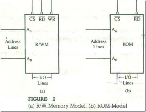
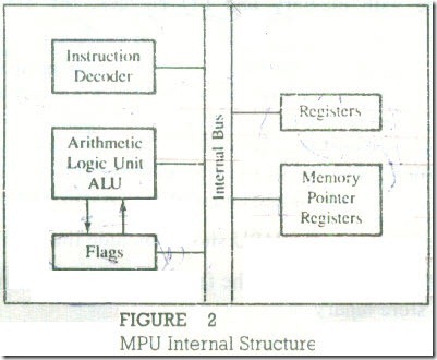
SUMMARY In this chapter, we examined the requirements of the Microprocessor Unit (MPU) to communicate with memory and I/O devices and to process binary data. Based on those requirements, we designed a generalized model of the M PU. We discussed memory in terms of its storage elements, namely, latches and registers and techniques of assigning addresses. The steps required for the MPU to communicate with memory and I/Os were briefly described. The impor­tant concepts are summarized as follows. · The MPU performs four primary operations: Memory Read, Memory Write, I/O Read, and I/O Write. · To communicate with memory and I/Os, the MPU needs three types of buses: the unidirectional address bus to send memory and I/O addresses, the bidirec­tional data bus to transfer data, and control signals to enable the devices. · The MPU should have signal lines to accept and to acknowledge external re­quests. These requests are Reset (go back to beginning), interrupt ( stop the ongoing proces...

EXAMPLE OF A MICROPROCESSOR-BASED SYSTEM

Image
EXAMPLE OF A MICROPROCESSOR-BASED SYSTEM In the last three sections, we discussed a generalized MPU model. prime memory and its organization model. and I/Os. The discussion can be summarized in the block diagram of a microprocessor-based system as shown in Figure 14. It in­cludes a generalized MPU, two types of prime memory. and two I/O devices. All address lines are used to address memory. and only the low-order ad­dress bus is used to identify I/O devices, indicating that they are connected as peripheral-mapped I/O (the details of Chip Select decoding are omitted here). The MICROPROCESSOR-BASED SYSTEM: MPU, MEMORY, AND I/O data bus is bidirectional and common to all devices. The four control signals gen­erated by the MPU are connected to different peripheral!" as shown in Figure 2.14. HOW DOES THE SYSTEM WORK? Let us assume that a simple program with three instructions is already written and stored in binary in R/W memory. Those instructions are 1. Read on/off swit...

INPUT AND OUTPUT (1/0) DEVICES

INPUT AND OUTPUT (1/0) DEVICES Input/Output devices are the means through which the MPU communicates with "the outside world." The MPU accepts binary data as input from devices such as keyboards and analog-to-digital (A/D) converters and sends data to output devices such as LEDs or printers. There are two different methods b which an MPU can identify I/O devices :one uses an 8-bit address and the other a 16- bit address These methods are described briefly in the following sections. I/Os with 8-Bit Addresses (Peripheral-Mapped I/O) In this type of I/O, the MPU uses eight address lines to identify an input or an output device; this is also known as peripheral-mapped I/O .The eight address lines can have 256 (28 combinations) a dresses ;thus the MPU can identify 256 input devices and 256 output devices with addresses ranging from 00 H to FF H · The input and output devices are differentiated by the control signals I/O Read for input devices and I/O Write for output device...

Memory Classification

Image
Memory Classification Memory can be classified into two groups: prime(or main) memory and storage memory .The RIWM and ROM discussed in the last section are examples of prime memory; this is the memory the microcomputer uses in executing and storing programs. This memory should be able to respond fast enough to keep up with the execution speed of the microprocessor. Therefore. it should be random-access memory, meaning that the microprocessor should be able to access information from any register with the same speed (independent of its place in the chip). Storage memory includes examples such as magnetic disks and tapes (see Figure 13). This memory is used to store programs and results after the comple­tion of program execution. Information stored in' these memories is nonvolatile, meaning information remains intact even if the system is turned off. Generally, these memory devices are not a part of any system; they are made part of the system only when stored programs need to b...

Memory Map

Image
Memory Map Typically, in an 8-bit microprocessor system, 16 address lines are available for memory. This means it is a numbering system of 16 binary bits and is capable of identifying 2 16 (65,536) memory registers. each register with a 16-bit address. The entire memory addresses can range from 0000 to FFFF in Hex. A memory map is like a pictorial representation in which memory devices are located in the entire range of addresses. Memory addresses provide the locations of various memory devices in the system, and the interfacing logic defines the range of memory ad­dresses for each memory device. Figure 9 (a) RIW Memory Model; (b) ROM Model Now let us assume that we have a memory chip with 256 registers that needs only eight address lines (2 8 = 256). How can we assign 16-bit addresses to 256 registers? This can be accomplished by using the remaining eight lines for the Chip Select through appropriate logic gates as illustrated in the next example. Example 1 Illustrate...

MEMORY

Image
MEMORY Memory is an essential component of a microcomputer system; it stores binary instructions and data for the microprocessor. There are various types of memory, and they can be classified in two groups: prime (or main) memory and storage memory. In the last chapter. we saw two examples of prime memory: Read/Write Memory (R/WM) and Read-Only Memory (ROM). Magnetic tapes and disks can be cited as examples of storage memory. First. we will focus on prime memory and then briefly discuss storage memory when we examine various types of memory. The R/W memory is made up of registers, and each register has a group of flip-flops or field-effect transistors that store bits of information. The user can use this memory to hold programs and store data. On the other hand, the ROM stores information permanently in the form of diode ; the group of diodes can be viewed as a register. In a memory chip. all registers are arranged in a sequence and iden­tified by binary numbers called memory add...

Microprocessor as a Processing Unit

Image
Microprocessor as a Processing Unit When the microprocessor executes instructions, it does so in a continuous se­quence of fetch, decode, and execute operations. After examining these opera­tions in more detail, we can describe the requirements of the internal architecture of our generalized microprocessor. FETCHING AN INSTRUCTION To fetch an instruction, the microprocessor places a memory address on the ad­dress bus and reads binary information using the data bus .Therefore, it needs a register that can hold memory addresses and increment these addresses after the fetching is completed, a sort of memory pointer. DECODING AN INSTRUCTION Once an instruction byte is fetched,' it needs to be decoded to answer the following: · Is it a complete instruction? If not, how many more bytes need to be fetched? · What type of operation is required and on what data ? To perform these functions. the microprocessor needs an instruction decoder that can interpret the fetched binary...

Microprocessor ­Based System : MPU, Memory, and 1/0

Image
Microprocessor ­Based System : MPU, Memory, and 1/0 A microprocessor-based system consists pri­marily of three components-the micropro­cessor unit (MPU). memory. and I/O (input / output). The MPU is the central player; it com­municates with memory and I/O devices. pro­cesses data, and controls timing of all its oper­ations. In this chapter. we will examine what the MPU does and what its requirements are. We then design a model for a generalized MPU that expands on the bus concept discussed in the previous chapter and shows signals neces­sary for the MPU to communicate with other devices. The model also describes the require­ments for processing data and shows registers and logic circuits the MPU needs. Memory and 1I0s are integral parts of a microprocessor-based system. We will discuss memory in terms of its basic elements-latches and registers-and specify the requirements for a memory chip to store information and com­municate with the MPU. Based on those re­quirements, we then de...

SUMMARY Of Microprocessors, Microcomputers, and Assembly Language

SUMMARY The various concepts and terms discussed in this chapter are summarized below: Computer Structure · Digital Computer-a programmable machine that processes binary data. It includes four components: CPU (ALU plus control unit), memory, input, and output. · CPU -the Central Processing Unit. The group of circuits that processes data and provides control signals and timing. It includes the arithmetic/logic unit, registers, instruction decoder, and the control unit. · ALU -the group of circuits that performs arithmetic and logic operations. The ALU is a part of the CPU. · Control Unit -The group of circuits that provides timing and signals to all operations in the computer and controls data flow. · Memory -a medium that stores binary information (instructions and data). · Input -a device that transfers information from the outside world to the computer. · Output -a device that transfers information from the computer to the outside world. Scale of Integration ...

MICROPROCESSOR INSTRUCTION SET AND COMPUTER LANGUAGES

Image
MICROPROCESSOR INSTRUCTION SET AND COMPUTER LANGUAGES Microprocessors recognize and operate in binary numbers. However, each micro­processor has its own binary words, instructions, meanings, and language. The words are formed by combining a number of bits for a given machine. The word (or word length), as defined earlier, is the number of bits the microprocessor rec­ognizes and processes at a time. The word length ranges from 4 bits for small, microprocessor-based computers, to 32 bits for such large computers as the IBM ES 9000 series. Another term commonly used to express word length is byte. The ,byte is defined as a group of eight bits. For example, a l6-bit microprocessor has a word length equal to two bytes. The term "nibble," which stands for a group of four bits, is also found in popular computer magazines and books. (A byte has two nibbles.) TABLE 1 Microcomputer Applications   The instruction is defined as a complete task (such as Add) the microproces­...